The picture below shows the interior of a ”stock” Vivitar 283 module. You can see the two contacts that are “shorted” (soldered together). You can also see the two contacts that will be connected to the resistors, the ones with the red and black wires attached. (This picture is from the standard 283 sensor that included a photocell for “automatic exposure”. When used solely with resistors, there are no “polarity “ concerns).
Note that there is a 200pF capacitor across the leads to the variable resistance. Prior to using 283’s for microscope illumination I had used them for many years for other “high speed” photography projects. The controls I used for those projects did not have this small capacitor, and they worked fine. Since Vivitar made their modules with this component in place I assume there was a reason... so I incorporate it in my modification.

Note: As mentioned above this flash model was made for many years. The earlier models had a high voltage across the sync terminals. The voltage levels are too high for some of the newer electronic cameras, and could seriously damage these cameras. Units that were made later in the products life span had a much lower, safe, sync voltage level. While units manufactured in Korea or China are often said to be safe for all cameras, I would err on the cautious side. If you have the proper meter and knowledge to check the unit you will be using, you can measure it and compare the results to your camera specs (if you can find them!).
A worry-
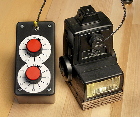
The picture below shows a finished “control box” and a flash unit.
I have used two 12-
The center contact is not used.
The two contacts on the left side of the picture above, one at "10 o'clock" the other at "8 o'clock" must be connected ("dead short") to each other.
Using the Vivitar 283 for Photomicrography
A versatile manual power control for the Vivitar 283
My desire to photograph active, live subjects through the microscope necessitated the use of electronic flash. This page does not cover the method used to implement the flash illumination on the microscope, but provides information about controlling the light output (and as a result the flash duration) with the Vivitar 283 flash unit. If you wish to see how the flash unit was incorporated into the microscope illumination see the page on my current setup, as well as an earlier implementation.
I settled on using the venerable Vivitar 283 primarily because it allows easy and
remote (via wire) setting of power levels. The lower power levels give very short
flash durations that have great motion stopping ability. I had tried using a TTL
flash unit, but found I wanted to make + or -
Vivitar made a “VariPower” module for this flash, and they also made a remote cord
so that this module could be used some distance from the flash. The VariPower is
nothing more than a simple (but custom) variable resistor. I have always found the
VariPower hard to reset to exact values, or in small increments. It was intended
to plug into front of the flash, so it is necessarily small. The adjustment is non-
_________________________________________
The picture below shows the two contacts on the front of the unit that are used to
change power levels. You only need to vary the resistance between these contacts.
The control box I now use is set up using multi-
* all units went down to at least -
Full Power
-
-
-
-
-
-
-
-
-
-
-
-
-
-
-
-
250K ohm or greater
150,000 ohm
78,400 ohm
57,000 ohm
35,290 ohm
26,500 ohm
17,720 ohm
12,350 ohm
9,550 ohm
7,600 ohm
5,680 ohm
4,400 ohm
3,150 ohm
2,400 ohm
1,530 ohm
800 ohm
155 ohm

To determine the values for the resistors, four Vivitar 283's (all were "used" units) were carefully tested. Using a Sekonic flash meter, the resistance values required to decrease the power in "stops" were determined. There was a small difference from unit to unit. The values listed here are the average, and they have proven to work well.